Logging your Raspberry Pi's Input Pins in C
Posted: 6th February 2022Introduction
Lately, I wanted to work a bit more "low-level" again, using my favourite programming language -- C. For this reason, I decided to dust of my old Raspberry Pi Model 3B+ and write a little program for it, which logs the states of its general purpose input/output (GPIO) pins. Its source code is now available on my github.
In this post, I summarise some points I have learned during this project for future reference.
Setting up the WiringPi Library
First, we install the C library WiringPi. If you use the regular Raspbian Pi OS with desktop support, the library should already be included. However, it's not part of the Lite version which I use, so I had to google around a bit and manually install it following these instructions.
Long story short, run the following commands in the command line of your Raspi:
# Installing git for downloading
sudo apt-get install git-core

# Purge potential earlier version of WiringPi
sudo apt-get purge wiringpi
hash -r

# Download latest version of WiringPi
git clone https://github.com/WiringPi/WiringPi.git
cd WiringPi
git pull origin

# Build WiringPi on your machine
./build
The Pin Layout
To properly address the GPIO pins, we need to find out which GPIO pin number is mapped onto which (physical) pin of the circuit board. For instance, the Model 3B+ maps GPIO2 onto the physical pin number 3, GPIO 27 onto pin number 13, etc.
Here, you can find the complete pin mappings. Be aware that they differ between the different models of the Raspberry Pi, so please make sure to use the right one, since connecting the wrong pins with each other may or may not destroy your hardware.
Alternatively, you may use the command gpio readall to inspect the pin mapping for your specific device. For my Model 3B+, I get:
pi@raspberrypi:~ $ gpio readall
 +-----+-----+---------+------+---+---Pi 3B--+---+------+---------+-----+-----+
 | BCM | wPi |   Name  | Mode | V | Physical | V | Mode | Name    | wPi | BCM |
 +-----+-----+---------+------+---+----++----+---+------+---------+-----+-----+
 |     |     |    3.3v |      |   |  1 || 2  |   |      | 5v      |     |     |
 |   2 |   8 |   SDA.1 |   IN | 1 |  3 || 4  |   |      | 5v      |     |     |
 |   3 |   9 |   SCL.1 |   IN | 1 |  5 || 6  |   |      | 0v      |     |     |
 |   4 |   7 | GPIO. 7 |   IN | 1 |  7 || 8  | 0 | IN   | TxD     | 15  | 14  |
 |     |     |      0v |      |   |  9 || 10 | 1 | IN   | RxD     | 16  | 15  |
 |  17 |   0 | GPIO. 0 |   IN | 0 | 11 || 12 | 0 | IN   | GPIO. 1 | 1   | 18  |
 |  27 |   2 | GPIO. 2 |   IN | 0 | 13 || 14 |   |      | 0v      |     |     |
 |  22 |   3 | GPIO. 3 |   IN | 0 | 15 || 16 | 0 | IN   | GPIO. 4 | 4   | 23  |
 |     |     |    3.3v |      |   | 17 || 18 | 0 | IN   | GPIO. 5 | 5   | 24  |
 |  10 |  12 |    MOSI |   IN | 0 | 19 || 20 |   |      | 0v      |     |     |
 |   9 |  13 |    MISO |   IN | 0 | 21 || 22 | 0 | IN   | GPIO. 6 | 6   | 25  |
 |  11 |  14 |    SCLK |   IN | 0 | 23 || 24 | 1 | IN   | CE0     | 10  | 8   |
 |     |     |      0v |      |   | 25 || 26 | 1 | IN   | CE1     | 11  | 7   |
 |   0 |  30 |   SDA.0 |   IN | 1 | 27 || 28 | 1 | IN   | SCL.0   | 31  | 1   |
 |   5 |  21 | GPIO.21 |   IN | 1 | 29 || 30 |   |      | 0v      |     |     |
 |   6 |  22 | GPIO.22 |   IN | 1 | 31 || 32 | 0 | IN   | GPIO.26 | 26  | 12  |
 |  13 |  23 | GPIO.23 |   IN | 0 | 33 || 34 |   |      | 0v      |     |     |
 |  19 |  24 | GPIO.24 |   IN | 0 | 35 || 36 | 0 | IN   | GPIO.27 | 27  | 16  |
 |  26 |  25 | GPIO.25 |   IN | 0 | 37 || 38 | 0 | IN   | GPIO.28 | 28  | 20  |
 |     |     |      0v |      |   | 39 || 40 | 0 | IN   | GPIO.29 | 29  | 21  |
 +-----+-----+---------+------+---+----++----+---+------+---------+-----+-----+
 | BCM | wPi |   Name  | Mode | V | Physical | V | Mode | Name    | wPi | BCM |
 +-----+-----+---------+------+---+---Pi 3B--+---+------+---------+-----+-----+
In this diagram, "Physical" represents the pin's physical position on the circuit board, whereas "BCM" refers to the GPIO number of the pin.
The actual Logger
Now it's time for the actual logger. I will not go through the source code line by line, but instead highlight some of its more noteworthy and interesting aspects.
Setup
The function init_gpio() sets up the Raspi for use as logger. It first calls WiringPi's setup function wiringPiSetupGpio(), and then switches all GPIO pins we want to monitor in input mode and pulls them to UP (+3.3V) state. Thus, we will be able to detect events which physically connect a GPIO pin with a GND (0V) pin of the circuit board. The opposite (pulling the GPIO to DOWN, detecting its physical connection to a +3.3V pin) would of course be equally possible. Thus, we run:
void init_gpio() {
    /*
     * Setup all desired GPIO pins for use as input
     * and pull them to UP
     */

    // Setup GPIO usage
    wiringPiSetupGpio();

    // Set all desired GPIO pins to input mode and UP
    for (int i = 0; i <= NB_PINS; i++) {
            pinMode(PINS[i], INPUT);
            pullUpDnControl(PINS[i], PUD_UP);
    }
}
Interrupt Binding instead of regular Polling
Instead of automatically polling the GPIO states once every few milliseconds, we make use of the Raspi's interrupt system. We can define an interrupt handler function which is called whenever a pin of interest changes. We do so as follows:
// Bind interrupt to handler
for (int i = 0; i < NB_PINS; i++) {
    wiringPiISR(PINS[i], INT_EDGE_BOTH, &handle);
}
Here, void handle() is the handler function to be called. The only downside to this approach is the fact that WiringPi does not support passing any parameters to the interrupt handler function. Thus, we have to find out within the handler function which pin has changed by comparing the current pin states to an int array containing the previous state of each pin. This array needs to be global so that we may access it from within the function.
Contact Bounce
When using interrupts instead of regular polling, we run into the problem of contact bounce. This refers to the fact that pressing a physical button will not give a perfectly clean signal jumping from UP to DOWN (or vice versa). Instead, there will be a short perioud of time in which the signal randomly bounces around, causing a burst of interrupts. This oscilloscope measurement nicely illustrates the problem:
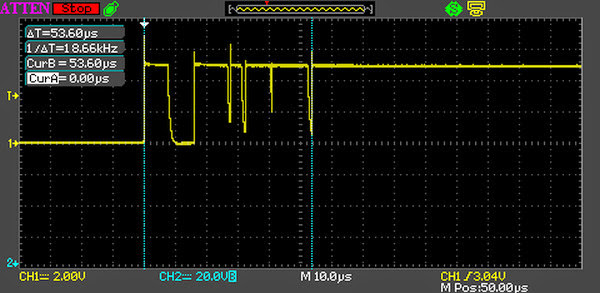
Thus, we extend our approach of a global int array of the pins' previous state to a global array of structs which also contain the timestamps associated with the previous states.
Because C's time() function only provides full seconds but contact bounce happens on the order of microseconds, we save a pin's last state's seconds and additional microseconds in the following structure:
struct timedstate {
    int state;
    time_t time_of_state_secs;
    int additional_usecs;
};
Saving the pins' state to the global array of structs then is done as follows:
void record_last_state() {
    /*
     * Record current state and time to LAST_STATE_WITH_TIME.
     */

    // Get current seconds and microseconds
    struct timeval tv_now;
    gettimeofday(&tv_now, NULL);

    // For all pins:
    for (int i = 0; i < NB_PINS; i++) {
        // Read pin state
        LAST_STATE_WITH_TIME[i].state = digitalRead(PINS[i]);

        // Save seconds
        LAST_STATE_WITH_TIME[i].time_of_state_secs = tv_now.tv_sec;

        // Save additional microseconds
        LAST_STATE_WITH_TIME[i].additional_usecs = tv_now.tv_usec;
    }
}
This allows us to discard all events of a pin which happen within a certain predefined time interval (I use 200ms) after a previous event of the same pin.
Heap Fragmentation and Parameter Passing
Because the logger should be able to run over longer periods of time and to record a lot of events, we need to make sure to not fragment our heap; otherwise our program might run out of memory at some point of time. This is done by strictly avoiding all repeated memory allocations and freeing. To do so, we allocate all heap memory we ever need upon startup and keep reusing it:
// Context: Outside of main()

// We only ever use these two arrays to avoid repeated malloc() and free().
struct timedstate* LAST_STATE_WITH_TIME;
int* CURRENT_STATE;
We also gain a slight performance increase by not passing around pointers to these arrays, but instead keeping them global and accessing them from within functions. For instance, recording the current state to CURRENT_STATE is done with the following function:
void record_current() {
    /*
     * Query all desired GPIO pins and write status to CURRENT_STATE
     */

    for (int i = 0; i < NB_PINS; i++) {
        CURRENT_STATE[i] = digitalRead(PINS[i]);
    }
}
Traditionally, this would be seen as "bad style" due to global state, but because we need to keep LAST_STATE_WITH_TIME global anyway (because we cannot pass parameters to handle()), I think there is no shame in being consistent and keeping CURRENT_STATE global as well. Additionally, the slight gain in performance and the fact that the project is small and thus easy to reason about in my opinion further justify this choice.
Conclusion
This was a nice little project to finally work again in the C programming language and to get a bit "closer to the metal." Especially the problem of contact bounce was completely new to me and something I enjoyed solving. Feel free to reuse the final program and provide feedback in case you see room for optimisation :).